


Abs: Active soil gas methods consist of the withdrawal and analysis of the soil gas from the subsurface. These methods give concentration data (for example, μg/m3) for COCs, which can be directly compared to risk-based screening levels or used in predictive models.

Active soil gas methods consist of the withdrawal and analysis of the soil gas from the subsurface. These methods give concentration data (for example, μg/m3) for COCs, which can be directly compared to risk-based screening levels or used in predictive models. Two techniques are most commonly used to install soil gas probes to collect external active soil gas samples – driven probe rod and burial of soil gas sampling tubes.
Driven Probe Rod

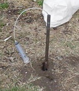
Figure 1: driven probe rod
This method consists of the insertion of a hard rod (probe) driven to a target depth, collection of soil gas through the rod while it is in the ground, and subsequent removal of the rod. Typically, probes are constructed of hollow steel rods with an external diameter ranging between 12.5 mm and 50 mm (0.5 inches and 2 inches). Small diameter inert, replaceable tubing runs down the center of the drive rod to eliminate potential contamination from the inside of the rods. The probes can be driven by hand methods, direct-push systems, or with larger drill rigs using a wire-line hammer. Probe installation can be difficult in over-consolidated or coarse-grained soils. A surface seal is usually used, but this seal does not prevent cross-flow at greater depths, so driven probes are most applicable in relatively uniform moderate to high permeability materials (generally not in low permeability soils).
Burial of Soil Gas Sampling Tubes

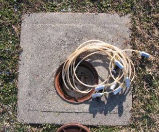
Figure 2: typical configuration of nested well
This method consists of the burial of a small diameter (typically ⅛ inch to 1 inch outer diameter) inert tube or pipe (stainless steel, Teflon, polyvinyl chloride, high density polyethylene, polyether ether ketone, Nylaflow, or similar) to a target depth with subsequent sampling of the soil gas after a period of time. Tubing may be buried in holes created with hand driven rods, direct-push systems, hand-augers, drills (for sub-foundation samples) or drill rigs for deeper samples. Clean sand is used as backfill around the tip, and the remainder of the borehole annulus is sealed, usually with a bentonite and water slurry. This method offers significant advantages when repeated sampling events are needed, or where the geology is not conducive to driven probes. Multiple tubes can be “nested” in the same borehole, if the seals between intervals are tight, and are often referred to as multilevel soil gas wells or nested probes.
Soil Vapor Probe Materials/Construction
It is important that the correct soil vapor probe materials are used and the probes constructed properly. Following are recommended materials and construction issues for soil vapor probes.
Use tubing material that does not adsorb or off-gas volatile hydrocarbons. nylon, Teflon, and stainless steel all give comparable results for typical PHCs. For heavier molecular weight compounds, stainless steel shows the least adsorption, but may be impractical to use. Nylon is recommended over Teflon tubing, because nylon tubing is less expensive and the compression fittings are easier to seal. Polyethylene tubing, commonly used by direct-push firms for groundwater sampling, should not be used for soil vapor samples because the polyethylene tubing has been shown to adsorb hydrocarbons.

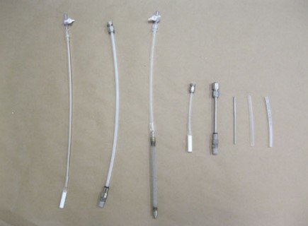
Figure 3: Vapor sample materials, including ⅛-inch outer diameter tubing, three types of tips (ceramic, aluminum, and braided steel) and two types of surface terminations (stopcock and Swagelok fitting).
Nominally ⅛-inch or ¼-inch outer diameter tubing is recommended. Stainless steel, aluminum, ceramic, or plastic (choice depends upon project specifications) are used for probe tip material. Swagelok fittings or plastic valves (two-way plastic valves or stop cocks) are best for sealing tubing that will remain in the ground for an extended time. Options for surface termination include flush mounts on the floor/surface, belowground termination (with or without a locking cover), and various aboveground completions that are commercially available.
Equipment Blanks
Collection of an equipment blank is recommended for all VI investigations, especially if metal probe tips are used. Zero-grade air or nitrogen should be drawn through the probe tubing, probe tip, and the sampling train at the start of the field program. The collected sample should be analyzed for the same compounds as the soil vapor samples. This practice confirms that the metal probe tips and other probe parts are clean before putting them in the ground.
Equilibration Time
When probes are installed, the in situ soil vapor can be displaced and a period of time is required for the soil vapor to re-equilibrate to their pre-disturbed values. The following equilibration times were required to reach 80% of the final value, assumed to represent the pre-disturbed value in fine-grained soil:
- Sampling through probe rod installed by hand: 15 minutes
- Sampling through probe rod installed with direct-push methods: 30 minutes
- Sampling through probes where tubing is buried in a sand pack in the ground: 8 hours
For collection systems with large purge volumes or designed to collect large sample volumes, it is often necessary to seal the probe at the surface. Seals may also be necessary for small volume systems if the soils are extremely porous and the sampling depth is close to the surface (less than 3 feet). The most common sealing technique is to grout the surface contact of the probe.
Purging the Probe and Sampling Train
The sample collection equipment used for soil vapor surveys has an internal volume that is filled with air or some other inert gas prior to insertion into the ground. This internal volume must be completely purged and filled with soil vapor to ensure that a representative soil vapor sample is collected. Probe purging is typically accomplished using a pump or a syringe equipped with a three-way valve. Syringes are an inexpensive and simple approach for purging small volumes up to 1 liter. For larger purge volumes, a pump with variable flow rates and a flowmeter is more efficient. At a minimum, enough vapor should be withdrawn prior to sample collection to purge the probe and collection system of all ambient air or purge gas (1 purge volume).

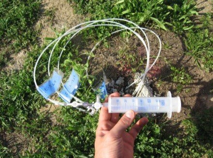
Figure 4: purging with a syringe
Flow Rate and Applied Vacuum During Sampling
To minimize the potential desorption of contaminants from the soil, soil gas samples should be collected using techniques that minimize the vacuum applied to the soil. Higher vacuums also increase the potential for leaks in the sampling system. Most agencies require flows less than 200 mL/min. For relatively coarse-grained soils (high permeability), flow rate does not appear to be an important variable for soil gas concentration. The vacuum can be tested with pulling the syringe plunger or using a vacuum gauge placed between the probe and sample container.
Leak Tests
Leaks in the sampling train or leaks of ambient air into the probe tubing can result in diluting the soil vapor samples with ambient air and will result in underestimating actual contaminant concentrations in subsurface soil gas. Excessive vacuum conditions resulting from low porosity soils or high moisture content soils may exacerbate the potential for ambient air leakage. Two methods of leak detection are recommended: (1) performing a “shut-in” test of the sampling train and applying a leak detection compound or water to the vapor probe at the surface or (2) applying a tracer gas over the probe and over the entire sampling apparatus.
The shut-in test is performed by sealing the sampling train from the vapor probe tubing termination to the sample container (such as a Summa canister or Tedlar bag) and applying a vacuum to the sampling train. The applied vacuum should hold steady (not decrease) for at least 30 seconds. The start and end vacuum should be recorded and reported. If the sampling train does not hold the vacuum, then all connections should be rechecked and the shut-in test repeated. Once the shut-in test has been successfully completed, a leak check compound or water is applied to the surface completion of the probe. (figure 6 and 7)

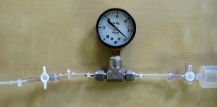
Figure 5: Simple sampling train arrangement for a shut-in test using a syringe as the vacuum source.

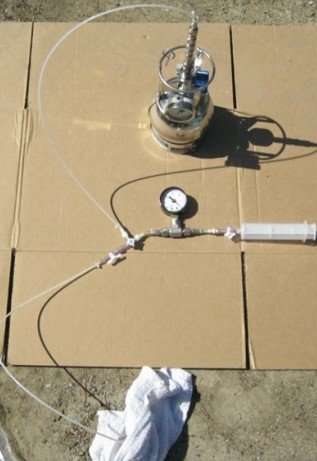
Figure 6: Sampling arrangement showing probe tubing, leak check compound soaked into towel covering the probe at the ground surface.

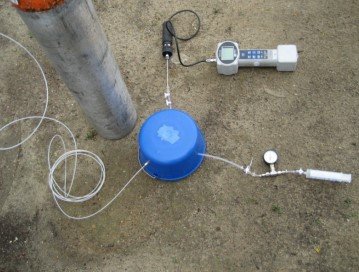
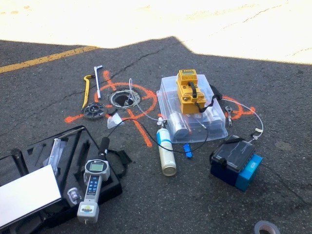
Figure 7. Gas shroud over Vapor Probe Surface Completion. System consists of shroud (blue bucket), helium cylinder, field helium detector and syringe with vacuum gauge for purging.
Method 2 involves enclosing the entire sampling apparatus, including sample container, all tubing and connections, and the vapor probe surface completion in a shroud, which is filled with a tracer (see Figure 8).

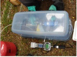
Figure 8: Covering the entire sampling system and probe with a shroud.
For the methods described above, measure both the concentration of tracer compound in the shroud and the concentration of tracer compound in the soil vapor sample in the field using a handheld field meter or with an on-site lab. If canisters are being used, measure the tracer in the probe tubing after purging and prior to opening the canister. If the tracer concentration in the probe tubing is greater than 15 of the concentration in the shroud, then the leak should be found and corrected before opening the canister. After the canister has filled, test the probe tubing again. If the tracer concentration in the probe tubing is greater than 15% of the concentration in the shroud, then the sample in the canister may be compromised. The soil vapor sample in the canister should then be tested for the tracer at the laboratory.
Collection of Samples
There are several sample collection methods that can be used for soil vapor.
Active Soil Gas Sample Collection into Passivated (Summa) Canisters
After purging, the canister should be connected to the probe tubing, but not opened, before applying the leak detection compound. A vacuum gauge is used to measure the canister vacuum prior to sampling and the final vacuum after sampling. Prior to sampling, check the canister to ensure that sufficient vacuum is present. Laboratories typically place a vacuum of approximately 28 to 30 inches Hg on the canisters prior to shipment to the site. After confirming the result of leak test, the canister can then be safely opened.

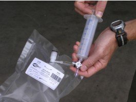
Figure 9: Filling a gastight bag using a syringe and three-way Luer valve.
Active Soil Gas Sample Collection into Gastight (Tedlar) Bags
After purging and application of the leak detection compound over the probe, soil vapor can easily be transferred from the soil vapor probe into a gastight bag using a syringe (figure 9). pumps upstream of the gastight bag should not be used because cross contamination between samples will occur. The gastight bag should be filled, while being careful not to overinflate and potentially compromise the bag seals.
Active Soil Gas Sample Collection into Gastight Glass Containers
Gastight glass vials and glass containers with valves or stopcocks can also be used for sample collection. Prior to sampling, the gastight vial should be evacuated to a vacuum of approximately -26 to -30 inches Hg with an electric vacuum pump or with a hand vacuum pump. A soil vapor sample is withdrawn using a syringe as described previously, except that a needle is placed on one side of the three-way plastic luer valve.

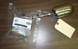
Figure 10: Transferring soil vapor sample from a gastight bag into a 400 cc canister
Active Soil Gas Sample Collection onto Adsorbents
Soil vapor can easily be transferred from the soil vapor probe onto an adsorbent using the same syringe and three-way plastic valve. The adsorbent tube is connected between the probe and the syringe so that the syringe pulls the soil vapor through the adsorbent (Figure 11).

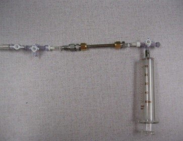
Figure 11: Sampling arrangement for adsorbent tubes
Other devices such as a low-flow pump can also be used to pass soil vapor over the adsorbent, but pumps upstream of the adsorbent should not be used as cross-contamination between samples will occur. Pumps should be calibrated before use to ensure correct measurement of volumetric flow. Also, the pump flow rate might change if the soil permeability changes. Sample flow rate should be to a flow rate of up to 50 mL/min for sampling in tight formations, and up to a maximum of 200 mL/min for sampling in permeable formations.
Sample Containers and Storage
For fuel related compounds (TPH, BTEX) and biogenic gases (CH4, CO2, and O2), allowable containers include Tedlar bags, gas tight vials (glass or stainless steel), and passivated stainless steel canisters (Summa). For halogenated compounds (such as TCE, TCA, and PCE), allowable containers must be gas tight, but also dark to eliminate potential effects due to photo destruction. Adsorbents are suitable for most VOCs and SVOCs.