


Abs: Vapor Intrusion (VI) occurs when vapors from contaminated groundwater or other subsurface sources migrate upward through vadose zone soils and into overlying buildings. While PVI has similarities to chlorinated vapor intrusion (CVI), recent research and analysis has increased the understanding of the significant differences between PVI and CVI.
Vapor Intrusion (VI) occurs when vapors from contaminated groundwater or other subsurface sources migrate upward through vadose zone soils and into overlying buildings. Figure 1 depicts a general conceptual site model (CSM) that summarizes site-specific conditions and describes the relationship between contaminant sources, contaminated media, migration pathways, and potential receptors for the VI process. However, some vapor effects in indoor air are not related to the VI pathway.
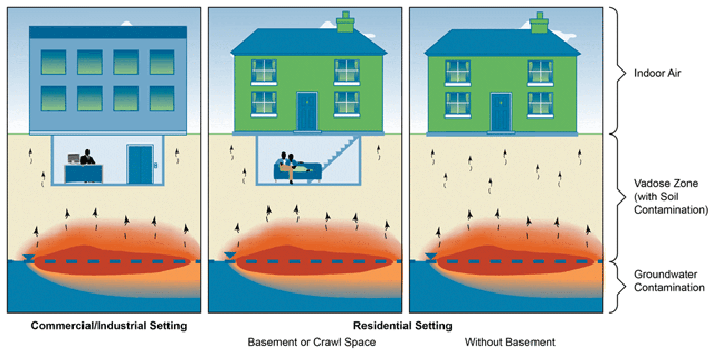

Figure 1. General conceptual site model for the VI pathway.
Differences Between PVI and CVI
While PVI has similarities to chlorinated vapor intrusion (CVI), recent research and analysis has increased the understanding of the significant differences between PVI and CVI. The defining feature of PVI that distinguishes it from VI of other volatile chemicals, is the relatively rapid rate of attenuation of petroleum hydrocarbons (PHCs) because of aerobic biodegradation in vadose zone soils. Table 1 summarizes key differences between PVI and CVI.
Table 1. General differences between PHCs and CVOCs (USEPA 2012g)
| Property | PHCs | CVOCs | PVI-related details |
| Distribution in
groundwater |
A significant portion of the source mass can reside above the water table as LNAPL. | The majority of free-phase product (DNAPL) migrates below the water table to a less penetrable layer. | l LNAPL will be mostly above groundwater
and spreading with changes in groundwater elevation. l Risk of PVI decreases when only dissolved phase is present. l Length of dissolved phase plumes is typically limited by biodegradation. |
| Biodegradation | Primarily aerobic; relatively rapid; biodegradation Interface is small (from a few inches up to 5 or 6 feet) – see Figure 3-1 | Primarily anaerobic (except vinyl chloride); relatively slow; generally limited to anoxic zones | l O2 in soil and water will promote biodegradation.
l Biodegradation will limit the size of the PHC vapor plume in the vadose zone. l Biodegradation will occur rapidly over a short distance in the presence of >2% O2 in soil gas. l Atmospheric O2 replenishment in the vadose zone is usually sufficient to continually support biodegradation. l Lack of O2 (<2% O2 in soil gas): o significantly decreases biodegradation rate o extends the distance vapors can travel before being biodegraded o may promote production of methane
|
| Biodegradation
products |
Aerobic conditions:
carbon dioxide (CO2) and water. Anaerobic conditions: methane and carbon monoxide (CO). |
Degradation chemicals generally are toxic. | l Terminal biodegradation products are
non-toxic. l Methane is a potential explosion hazard in presence of ignition source. l Methane production is generally increased by the presence of ethanol in fuels. |
Biodegradation
The fate and transport mechanisms, such as partitioning, diffusion, biodegradation, advection, and mixing explain the behavior of PHC vapors and describe how this behavior affects the PVI pathway.
- ● Process :Because rates of petroleum vapors biodegradation usually exceed the rates of petroleum transport via diffusion, petroleum vapors are typically, but not always, fully attenuated by aerobic biodegradation processes in the vadose zone. A notable feature of aerobic biodegradation of PHCs in soils is the short acclimation time for this process, which can be measured in hours and days (Turner et al. 2014).
- ● Environmental effects: Several environmental factors can hinder biodegradation. The most significant factor is the availability of O2. Some state regulations/guidance documents indicate that O2 levels only need to be greater than 2-4% by volume to support aerobic biodegradation. Some factors that may hinder the recharge of O2 in the vadose zone are soils with high moisture content, high organic content, low permeability, large building foundations and the presence of high PHC concentrations. Other factors that can potentially limit the biodegradation of PHCs include low moisture content, nutrient availability, temperature and heavy metals. In general, the rates of biological processes decrease with decreasing temperature. Heavy metal contaminants can be toxic to PHC-degrading bacteria and can decrease PHC degradation rates (Babich and Stotzky
1985). - ● Generation of methane and effects on biodegradation:Because methane is not a component of gasoline or other liquid hydrocarbon products, the presence of methane indicates that insufficient O2 is available for aerobic PHC biodegradation. The vertical screening distances discussed in Chapter 3 were developed in part from empirical site data for fuel releases that included 10% ethanol.
- ● Effects of PHC chemicals :Generally, for PHCs dissolved in the water phase, microorganism biodegrade n-alkanes (straight-chain alkanes) more rapidly than cyclic and aromatic compounds, and biodegrade shorter chain n-alkanes more slowly than longer chain n-alkanes (Alexander 1977). Another important factor that affects the biodegradability of a chemical based on its structure is the air-to-water partitioning coefficient. A greater fraction of the aromatic compounds are partitioned into water, are more readily available to be biodegraded, and therefore may be more significantly attenuated by microbial biodegradation than n-alkanes (DeVaull 2007).
PVI CSM
A CSM is a visualization of site conditions that allows for evaluation of contaminant sources and affected media, migration pathways, and potential receptors. This tool provides an iterative representation of the site and guides decision making while assessing the PVI pathway.
A CSM for PVI incorporates biodegradation and is used to determine whether a complete PVI pathway exists or, if needed, the information required to make this determination. Information to construct the CSM is acquired from historical research, site characterization, and an understanding of contaminant behavior, among other sources. The CSM is a dynamic tool that should be refined throughout the life of the project as new information is acquired.
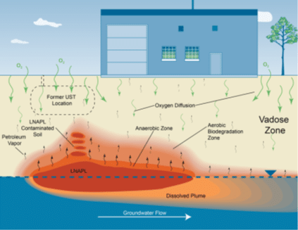

Figure 2 General conceptual site model for the PVI pathway
The Petroleum Vapor Intrusion Source
Petroleum fuels can be broadly categorized as “gasolines,” “middle distillates,” and “residual fuels,” with the middle category including diesel, kerosene, Stoddard solvent and some types of jet fuels (API 1994). The detailed chemistry of petroleum fuels has been extensively studied (Potter and Simmons 1998, USEPA 2009f). These fuels are primarily composed if hundreds of nonspecific, aliphatic hydrocarbon compounds with a small, variable amount of aromatic compounds, including BTEX and naphthalene. The vapors associated with petroleum fuels are similarly dominated by aliphatic compounds with smaller amounts of aromatic compounds (USEPA 2013a, Brewer et al. 2013).
Common types of petroleum sites
Petroleum products may be released to the environment at industrial, commercial, and residential properties. The type of site and PHC, as well as the nature of the release and subsurface lithology, influences the distribution of PHC in the subsurface.
Table 2 summarizes common types of petroleum sites and general features of each that may be related to the potential for PVI. The site type examples detailed in Table 2-2 are examples of common petroleum site types and may not cover all site type possibilities or all site-specific scenarios. Components of the sites listed may not be applicable to other types of petroleum sites. The characteristics summarized in Table 2-2 are characteristics as they relate to the potential for PVI.
Table 2. Types of petroleum sites
| Petroleum site type (link to Appendix E) | Common indicator compounds | Potential release sources |
| Gasoline and Diesel UST Locations | Gasoline: BTEX, tri- methylbenzenes, naph- thalene, methane Diesel: naphthalene, methane | USTs, product lines, dispensers, service bays |
| Commercial and Home Heating Oil Locations | Naphthalene, benzene | USTs, ASTs, product lines |
| Refineries | BTEX, naphthalene, methane | Underground or aboveground piping, USTs (former and current), ASTs, loading areas, tank pits (current and former), processing units, historical disposal sites |
| Bulk Storage Facilities | For oil/- petroleum/gasoline: BTEX, naphthalene, methane | Underground or aboveground piping, ASTs, oil/water separators, loading areas |
| Pipelines/Transportation | For oil/petroleum: BTEX, naphthalene, methane For natural gas: meth- ane, butane, propane, benzene | Pipeline, pipe joints, valves, flanges, weld points |
| Oil Exploration and Pro- duction Sites | BTEX, methane | Wells and well area, pipelines, gathering lines, mud pits, USTs and associated piping, ASTs and asso- ciated piping, maintenance facilities, oil/water separators |
| Former Manufactured Gas Plants (MGP) | BTEX, indane, indene, naphthalene, tri- methylbenzenes | Tar holders, oil/water separators, gas holder foundations, purifying boxes, tar wells |
| Coal Tar/Creosote Facil- ities | Naphthalene, alkyl-naph- thalene derivatives, benzene | Drip pads, product storage areas, unlined pits, lagoons |
| Dry Cleaners Using Pet- roleum Solvents | BTEX | Outside building (especially windows and doors), storage areas, dry wells, drains |