


Abs: Building control technologies are typically required at VI sites (in both existing and new buildings)until long-term, site-wide remedies reduce soil and groundwater concentrations to acceptable levels. The following sections discuss various VI building control technologies, factors affecting technology selection, and common design and installation issues.
Vapor control for VOCs can include environmental remediation, building mitigation measures, and institutional controls (ICs) to reduce or prevent VI from occurring. The management of vapors may be required at sites when the results of the site investigation phase indicate that indoor air concentrations of volatile compounds exceed mitigation screening levels in existing buildings or are likely to exceed screening levels in future buildings. Building control technologies are typically required at VI sites (in both existing and new buildings) until long-term, site-wide remedies reduce soil and groundwater concentrations to acceptable levels.
Several effective vapor control technologies may prevent the migration of vapors into a building and each have their advantages and disadvantages. One of the main considerations when evaluating each technology, however, is the long-term performance. CVOCs persist on site without active remediation of affected soil and groundwater. For these sites, the vapor control technology selected must operate over the long term or perhaps permanently. The exception to this practice is at VI sites with compounds associated with petroleum releases from underground storage tanks, where biodegradation can occur.
Passive Barriers
Passive barriers are materials or structures installed below or above a building foundation to physically block or limit the entry of vapors into a building. Passive barriers ideally cause soil gas that would otherwise enter the building under diffusion or pressure gradients to migrate beyond the building footprint. In reality, it may be difficult to completely prevent, or even substantially prevent, the entry of vapors into a building by passive barriers alone. Therefore, passive barriers are generally used in conjunction with passive venting. Any design of a passive barrier, however, should allow the venting system to be supplemented or upgraded to an active system or allow other measures to address inadequate performance.
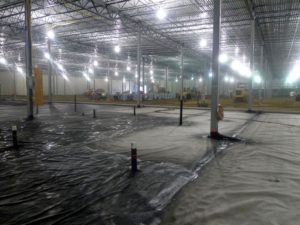
Most passive barriers consist of spray-on asphalt latex membranes, epoxy floor sealants, or low-permeability thermoplastic membranes. The design of a passive barrier should be supported by vapor diffusion coefficients, which assist in evaluating the liner’s effectiveness for the site contaminants present. In new structures, barriers are typically installed after the utilities are in place and below the lowest level (prior to the floor slab being installed). In existing structures, membranes can be used to retard the intrusion of vapors in crawl spaces or over dirt floors; however, in most circumstances their use requires the installation of an additional protective layer, which will increase the installation costs of the liner.
Passive barrier designs should include QA/QC plans to address the potential of damage to the membranes during installation, subsequent concrete pours, and building construction activities. It is also important that all future site activities include protocols for minimizing damage until a protective barrier (if necessary) has been installed. The QA/QC should also require thorough inspection of liner seals along all edges and at penetrations, observation during concrete pouring, and detailed procedures for testing the efficacy of the passive barrier after the slab is placed and (for example, pressure tests, smoke tests, and post-construction indoor air tests).
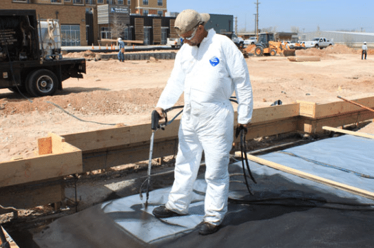

Figure 1: Spray-applied membrane
Most asphalt latex membranes are seamless, spray-applied, water-based membranes containing no VOCs, which provide a deterrent against VI. The membrane is typically installed prior to pouring the concrete slab and belowgrade vertical walls in order to fully encapsulate the building footprint. The membrane is typically sprayed onto a carrier geosynthetic (geotextile or thermoplastic membrane).
The epoxy floor sealant system is a vapor mitigation system that uses a chemically-resistant coating with a 100% solid epoxy blend. The system is designed to protect existing structures from VI without the need for additional concrete protection. Typical epoxy floor sealant systems can range between 10 to 60 mil and can be installed directly on top of an existing concrete slab. The epoxy floor sealant system is relatively new but appears to be effective, especially when used in conjunction with a passive venting system.
A thermoplastic is a type of plastic made from polymer resins that become a homogenized liquid when heated and a solid when cooled. Though not a common application, when applied as a liner, a thermoplastic can be used as a passive barrier that can provide relevant resistive and diffusive properties to protect against COCs. Many of these liners, however, can be easily damaged during normal construction activities, even when cushioned by sand. The potential for punctures may be reduced by using thicker membranes (for example, 60 to 100 mil HDPE or similar materials) and by using cushioning materials above or below the membrane, such as geotextiles, sand, or fine rounded gravel (pea gravel).
Subslab Venting System
SSV systems or passive subslab venting involves the placement of a venting layer below the floor slab to allow soil gas to move laterally beyond the building footprint under natural diffusion gradients (resulting from the buildup of soil gas below the building) or pressure (thermal or wind created) gradients.
Generally, passive venting is only feasible in new construction because of the need to install an engineered base layer beneath the lowest flooring layer. There are several venting systems that can be assembled and installed, including perforated pipe and low-profile vents.
Passive subslab venting systems generally result in less depressurization and lower air flow exchange rates than active depressurization systems with fans. As a result, passive venting systems require more permeable venting media, more suction pits for a given building area, more distributed collection pipes, and tighter passive barriers than active venting systems. In addition, passive venting systems are typically not installed as stand-alone systems and require sealing or barriers. In addition, consistent depressurization of the venting layer should not be expected from most systems.
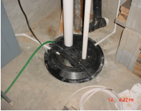

Figure 2: Passive sump mitigation system
Subslab (Active) Depressurization
SSD is a practical VI mitigation strategy suitable for most existing and new structures, including those with basement slabs or slab-on-grade foundations (USEPA1993). SSD systems function by creating a pressure differential across the slab that favors movement of indoor air into the subsurface. This movement is accomplished by pulling soil gases from beneath the slab and venting them to the atmosphere at a height well above the outdoor breathing zone and away from windows and air supply intakes. In new construction, SSD systems are similar to passive venting systems, except that a fan is used to draw soil gas through the subslab venting layer prior to discharging the soil gas to the atmosphere.
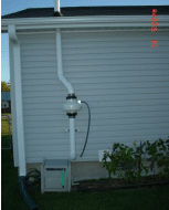

Figure 3. Active SSD system
Active mitigation systems, including SSDs, are the most reliable, cost-effective, and efficient technique for controlling VI in the majority of cases, with concentration reductions in the 90 to 99% range expected, and 99.5% or greater in carefully designed and installed systems. Subslab depressurization in the range of 0.025 to 0.035 inches H₂O is generally sufficient to maintain downward pressure gradients.
Hollow block wall or cinder block foundation walls may act as migration routes for vapor to enter homes, particularly if the holes in the top row of blocks are open. Therefore, mitigation techniques for block wall foundations include sealing the holes at the top, as well as depressurization of the block wall. Block wall depressurization is usually combined with subslab depressurization systems.
Submembrane Depressurization
SMD has been demonstrated to be the most effective mitigation method in crawl spaces, where a membrane is used as a surrogate for a slab to allow depressurization of the soil. Properly installed SMD systems have resulted in concentration reductions of up to 99.5%, similar to SSD system. For SSD, an impermeable membrane is used to cover the exposed dirt surface of a crawl space while the depressurization system withdraws soil gas from beneath the membrane and prevents soil gas intrusion into the space above.
The membrane must be well-sealed along all edges of the foundation wall or footings, and to any pipe penetrations through the membrane, with enough slack to prevent tearing of the membrane under stress. Because many homes have furnaces or utilities in the crawl space, it may be necessary to place pads or other protective materials over the liner to allow access to the crawl space without damaging the membrane. Membranes can easily be damaged or lose their seal at the edges; therefore, periodic inspection of membranes (or other performance testing) is needed for SMDs.
Subslab Pressurization
SSP systems are similar to SSD systems, except that fans are used to push air into the soil or venting layer below the slab, instead of pulling it out. This method increases the subslab air pressure above ambient levels, forcing soil gas from the subsurface to the sides of the building. USEPA suggests that this technology is most effective in highly permeable soils, where it may be difficult to pull enough air to depressurize the subslab region by SSD. SSP systems are applicable to both existing and new structures. Cracks or openings in the slab or foundation walls can cause short-circuiting of the system and air forced below the slab may reenter the building, potentially pulling in some of the vapors that the system intended to keep out. Because indoor air is typically used to force air below the slab, fans should be equipped with a filter to prevent buildup of debris in the vent system.
Building Pressurization/HVAC Optimization
As an alternative to other forms of VI mitigation, air within the structure can also be directed to air pollution control equipment (such as carbon adsorption systems) to remove toxic air contaminants from the building interior. This technique is not widely practiced, since it encourages the collection of contaminant vapors within the structure and depends on the treatment system’s uninterrupted performance to protect receptors.
This approach can be an effective mitigation strategy, however, when combined with other techniques to control vapor concentrations in problem rooms, or when building materials have been affected by PHCs. Indoor air treatment is an alternative to whole building pressurization when subsurface depressurization or pressurization methods are not feasible (for example, when high water tables and wet soils are present). Indoor air treatment is generally only applied in existing buildings, since more cost effective systems can generally be installed in new buildings.
Aerated Floor Systems
Aerated floors are concrete slabs with a continuous void space under the slab that can be used for subslab venting or depressurization in lieu of the sand or gravel venting layer commonly associated with traditional mitigation systems. Because the void space has very low resistance to air flow, vacuum levels and air exchange rates in the void space are generally higher and more uniform than in sand or gravel layers.
Aerated floors are typically constructed using proprietary plastic forms that are placed on the subgrade prior to pouring of the concrete slab. As a result, aerated floor systems are most applicable to new construction, although aerated floors can also be placed over existing slabs if a higher finished floor elevation can be accommodated. The total thickness of aerated floors (including both the void space and concrete) typically range from about 4 inches to several feet and are most commonly about 13 to 15 inches. The volume of concrete is similar to, or may be less than, the volume of concrete required for a traditional flat slab with the same load capacity.
Aerated floors can be designed for SSV or SSD operation (in the former case, air inlets are typically provided to increase air flow rates) and operated in either active and passive venting modes, depending on the degree of venting or depressurization needed to control vapor intrusion.